Basic Knowledge About Screw Type Briquetting Press
Basic Knowledge about operating a
screw type Briquetting press
Screw type briquetting press can produce biomass briquettes with higher compaction, it also has high energy consumption during the operation compared with mechanical
briquette machine. Because of the high friction, the mechanical wear on the screw type briquetting press is considerably higher than hydraulic and mechanical briquette machines. Therefore, the screw type briquette machine shall be maintained more frequently than other types of briquette machines. Especially the head of screw rod, which shall be polished and then welded with electrode rods that demands operators become capable of handling the compression ratio between the screw rod and sleeve in order to ensure the normal operation of briquette machine.
The most outstanding trait of this model is low investment for briquettes. Because the working principle of the screw type briquette machine is easier so it is easy to learn. Once the compression ratio is confirmed, the production yield will be quite smooth and the briquette machine will work with the capacity to the maximum. Therefore, the screw type briquette machine is more popular with clients from developing regions.
Fit clearance regulation for mixed feedstock:
1. Fit clearance between the compressing section of the threaded rod and the compressing section of the moulding cylinder.
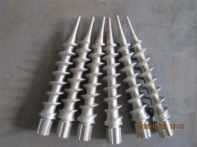
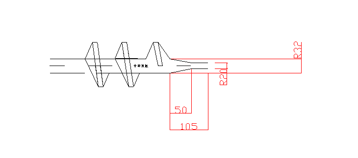
Compressing section of threaded rod (referring to the screw propeller, hereinafter also called CSTR) refers to tapered end of 5-7cm in the front of threaded rod.
Compressing section of moulding cylinder (referring to the sleeve, hereinafter also called CSMC) refers to tapered end of 6-8cm at the rear of moulding cylinder.
The briquetting press adopts tapered compressing chamber of 6-8cm, with the diameter difference in tapered compressing structure standing at 2cm.

The taper of the CSMC, also known as the conical degree, is generally 5°-7°while that of the CSTR 5°-7°(the above two shall usually remain approximate.) Lateral clearance between the two tapers above shall reach 2-4mm. As for the axial fit clearance between the front end of the threaded rod and the rear end of the moulding cylinder, 4-5cm shall be an ideal value, in particular for a new moulding cylinder, in which both the extruding speed and density will reach an optimally high value, thankfully, the CSMC and CSTR can endure abrasion to the maximum.
If manufacturing certain single material, please regulate spiral shaft values of the taper, height and length respectively (also known as the fit clearance between the CSMC and the CSTR).
Due to abrasion over the moulding cylinder, the CSMC will be concaved. Consequently, the front end of the spiral shaft shall be increasingly moved forward to keep the clearance in an optimal working condition. (Alternatively, the cylinder wear-resistant sleeve shall never be conducted in electrogas welding.)
2. Fit clearance between threaded rod and feeding sleeve:
The clearance value shall remain 2-4mm, namely, the diameter of the feeding sleeve 2-4mm larger than that of the threaded rod. Light and coarse material demands larger clearance, and vice versa. 6 grooves shall be engraved longitudinally on the feeding sleeve lest feeding skid occurs while due to the abrasion of the sleeve, 6 protruding lines shall be welded on the sleeve with the bulge thickness bigger than the diameter of the threaded rod.
3. Front end taper of the CSTR

From the front end of the threaded rod to the rear, the taper, also the conical degree comes from 90 degrees to 60 or 45 degrees. Emphatically, it shall coincide with the rear thread pitch, even larger than the rear thread pitch. Please see the sketch map above.
4. Front end diameter and taper of the CSTR
The front end diameter should cover a range of 45-50mm, with the taper conforming to that of the CSMC. Generally, a cover die shall be manufactured with the same size of the CSMC, which then will help confirm values for the front end diameter and taper of the CSTR.
5. Repair of the threaded rod
Because of the tough working environment (under the conditions of high temperature and high moisture and dry friction), the rod will be worn after a short period of service. Technically, it shall be amended every 40 hours. Apart from that, either improper fit clearance or impurity mixing up shall demand repair once every work shift. Even the best optimal condition can be fulfilled, but it can be used just for 120 hours continuously. The maintainer shall attach importance to repair of the threaded rod.
Repaired angle and size, both of which have been specified as above;
* Repair methods and materials needed;
* Please repair the rod based upon the specific wear-resistant material which roughly includes wear-resistant welding rods, anti-friction powder cake and powder. As for using the latter two powdery materials, a specialized welding gun shall be put into use (as required in the instruction manual). Economically, welding rods are a better option used with a DC welding machine. As to bead weld, please preheat the welding part. Welded parts shall be cooled into charcoal ash and ground with a grinder. The spiral length of the threaded rod covers several specifications to choose.
* To prolong the spiral rod, the front end can be extended or a spacer can be added along with the spline.
Supplementary Information
-
How to maintain the screw Propeller of a Briquetting Press?
Screw propeller is the main part and the most important forming mould (also called the die) in the briquetting chamber. And the Briquetting chamber consists of the space gap formed between sleeve (moulding cylinder) and the screw propeller.
1. Due to constant work within the high temperature and high moisture condition, the propeller is quite easily worn down in which pressure for briquetting will rarely be produced between moulding cylinder and propeller. Therefore, please change the abraded parts timely. The worn positions shall be patched with wear-resisting welding rods But as for the repair size, please accord with the specific wear degree. Generally, the repair work takes 3-5days. Disassembly methods: loosen bolts of the ring flange and the moulding cylinder can be smoothly pulled off.
2. All fastening parts such as bolts, belts, contactor of distribution board and circuit joints shall be inspected and tightened timely.
3. Bearings of the machine base shall be lubricated with high temperature grease (fit for 180℃and above). Lubrication methods: open the cover and conduct oiling into oil holes with an oil gun.
-
What should you pay more attention to for handling the Briquetting Press well?
1) Connecting the principle line, each copper sub-line shall have the diameter of no less than 6mm2. The working voltage shall remain stable lest the motor will be damaged.
2) No standing in front of the moulding cylinder during its work; do not use any metal tool to help charge material into the machine; do not mix any impurities with the material. Please pay more attention to the joints of heating ring in case of electric shock. By the end of work, all material on the hopper shall be used up and then push the “reverse run” button to have the main shaft reversely rotate.
3) If the screw propeller remains wrung, the reverse rotation of shaft shall never last 2 seconds, or the propeller will be pushed out and derailing from the main shaft.
4) The heated moulding cylinder shall be kept away from water, or it will get ruptured.
5) The temperature for moulding shall be proper and stable. Technically, too high temperature will result in fissured rods or cracked sticks while too low temperature ruptured propeller.
Note: the briquetting is generally decided by three factors which cover material moisture content, length of the threaded rod overlapping into the sleeve and work temperature. Please attach more importance to the above.
-
Difference with hydraulic briquetting press
By using the screwing procedure in Wood expert briquetting presses a continuous high output at low prime costs is guaranteed in contrast to hydraulic briquetting presses. In hydraulic procedures of pressure the pressure is generated by a pressure cylinder which performs construction-conditioned no pressing on the way back. In a
briquetting machine using the screwing procedure this task is performed by a screw which does not require a return.
During briquetting the source material gets strongly compressed and heated, whereby the lignin contained in the base material is released and assumes the function of an adhesive that holds the briquettes together. This process leads to high energy density and thus connected to high fuel homogeneity and to generally significantly improved fuel properties.
KMEC is a professional briquette machine manufacturer with years of experience. We supply all kinds of briquetting equipment, including hydraulic briquetting machine, mechanical stamping briquette machine, screw type briquette machine and other large
briquette plant and production line. If you want to develop the briquetting business, please feel free to contact us.
------------------------------------------------------------------------------------------------------------
Rice husk is a widely used agro waste for processing agro by-products, even though it seems useless. However, rice husk briquettes are quite useful as a kind of renewable green energy. You can realize biomass briquettes production with Kingman rice husk briquette machine and briquette plant.

